LED Controller Box Build - Holiday Doghouse Part 2
So, following up on the previous post “Holiday Doghouse Part 1,” the black and white beagle seemed to appreciate the remodeled doghouse and left me with paw-drawn schematics, a typewritten list of requirements, and a bunch of boxes delivered to my front door.
Oh, and he gave me 30 days to be done by Halloween.
I was intrigued, even excited, by what I saw drawn out, but never had I attempted such a project as he requested: an LED holiday display.
Reminder, I’m not even his owner. I don’t even have a dog; I’ve allowed this often-demanding beagle to set up his annual Christmas display on my front lawn for the past 13 years. And immediately after he handed me this task, he ran off to play a make-believe dogfight against his archenemy, the Red Baron.
Again, good grief.
Luckily, I had wanted to build a programable display for quite some time, so now I was ready to dig in!

Addressable LED Strips
Several years ago, I created a retro game cabinet with LED strip lights, but they were just RGB strips, and every LED had to be set to the same color. It is a nice effect for cabinets, shelves, room lighting, and small projects, but for holiday displays, they are very limited.
Enter Addressable LED Strips.
As the name implies, each LED, or pixel, on a strip is addressable, which means you can run patterns down the strip like chasing holiday light strings—but a thousand times cooler! Unlike the normal strips where you have a remote and a receiver, addressable LEDs require a microprocessor and, if you are hooking up a lot of them, a larger power supply.
I settled on the Dig Quad controller and Mean Well 300-watt power supply. I’ll mention more about these later.

Pixel Count
Each LED on a strip is considered a pixel, and each 5-meter (16.4-foot) strip comes in various densities.
- 30 pixels per meter
- 60 pixels per meter
- 100 pixels per meter
- 144 pixels per meter
Because the doghouse is small, I decided to use 60 pixels per meter to give it adequate coverage since there are some short runs. Depending upon your application and the number of feet you have to cover, you can choose a different pixel density. It should go without saying that the more pixels you have, the more power you will need to light them up. Also, power supplies and controllers have limits.
Less density allows you to see individual pixels; higher density blends them for a neon effect when used behind a diffuser. I wanted many lights in a small space and wasn’t going for neon, as I still wanted individual pixels to be seen from the street.
A standard 300-watt, 60-ampere power supply, and Dig Quad controller can handle 1,200 pixels or 20 meters (65.6 feet) at 60 pixels per meter. I measured all the edges of the doghouse and came up with slightly less than that, plus enough left over to do under the eaves! In the end, I planned on using 997 pixels, giving some headroom as you don’t want to run your power supply too close to its maximum.
I won’t go over all the calculations as it is a lot of math right now, but there are excellent tutorials, and I will go over my calculations in the next post when it is relevant to wiring.
Remember this as you plan and set your expectations: A 300-watt, 60-ampere power supply, and a Dig Quad controller can handle 1,200 pixels. Stay within that limit when calculating the number of feet to light and pixel density.
I had to talk Snoopy down from his original plans of a 3,600-pixel, 900-watt, 180-ampere display that would require three power supplies and three linked controller boards. He howled a little, even cried, but finally came around to my revised plan.
Controller
I do have my Ham radio license, and I am a software engineer. However, I’m not into soldering electronic components to a circuit board, nor am I all that into coding a microprocessor from scratch.
However, I like wiring things up, and luckily there are pre-built controllers and software out there to control addressable LEDs.
Enter Dig Quad and WLED.
First Build
To begin, I started bare bones on my dining room table with just six components:
- Dig Quad w/ WiFi
- Mean Well 300 watt 60-ampere power supply
- 3-prong power cord pigtail (16AWG)
- 16AWG wire
- 16AWG Ferrules
- LED addressable lights (I used BTF SK6812 60/m IP65, but any addressable lights will do, be sure to have your spec sheet handy)
This was my first build, and I just wanted to see the lights work without any smoke. By the end of this post, I’ll have upped my game and built a permanent control box.

So, for the first step, I hooked up the pigtail plug to the power supply. Note that you are working with AC wiring on this part, so be sure you know what hot, neutral, and ground are. If you are not comfortable with AC wiring, ask a friend and do your research.
Then, I connected a pair of DC power wires between the power supply and the Dig Quad controller power input terminals. Next, I connected a pair of DC power wires from the Dig Quad power out and data out terminals to an LED strip paying close attention to the 5v+/- and LED data wires.
I’ll talk more about how addressable strips work in the next post, but for now, it is important to know that there are three wires, a 5v positive (+), a data wire in the middle with an arrow which must run in only one direction, and a 5v negative (-) wire.
Before going too far, I visited Dr. Zzs site and watched the video DigQuad – Wiring & Installing WLED. Once set up, I sent mey first effect from the WLED app on my phone to the LED strip. Amazing! It worked!
For a first project, I could have just put this set up into a box, ran longer wires to the LEDs, and called it good, but I had a big project in hand, and I knew that if I was going to complete it, I needed a full control box build for the winter environment it would be installed in.
Control Box Build
Note: If you are doing your first small installation, you can get by with a small power supply, a DigUno, and a small waterproof lawn box. I’m powering just under 1,000 LEDs on a doghouse that sits outside for 4 ½ months of winter weather in sleet, heavy snow, and days on end of sub-zero (Fahrenheit) temperatures. I needed mine to be an outdoor, portable, expandable, re-purpose-able control box. What I ended up building meets my needs and is a little extreme for first builds. As I soon found out.
As I looked online for examples of how others mounted and protected their power supplies and controllers, I started developing a list of needs and wants. Fans for air circulation, a weatherproof box, and weatherproof connections.
Though it would be mounted and protected inside the doghouse, I needed it to withstand any water or snow that might fall inside if I needed to open the access roof. So, I needed a weatherproof box--with a clear cover, of course. I like seeing the internal wiring and LEDs, especially when all the components are organized and have status lights. Why did Doc Brown put the Flux Capacitor behind glass in such a prominent location? Because it was cool to marvel at.
I wanted it to be clean and organized, which meant I wanted to be able to mount the components to the base, incorporate proper cable management, and leave enough space for airflow and my fingers. I get easily frustrated when I can’t get my fingers in a case to wiggle, connect, or disconnect wires.
Among many “upgrades,” I opted to use a relay to save on power use. This allows the control board to be powered all the time (so I can manage it during the day) and provides power to the Power Supply Unit only when the lights should be on. This saves energy and helps give it a nice “complete” feel. I also added a physical “kill” switch for the 120 volt AC line in to quickly turn it off if something began to smell like burning. The 5 volt line to the control board does not have a kill switch. There is a post about wiring up a relay on the QuinLED site.
The control box wouldn’t be in the doghouse all year, I’d take it out when not on display, and it would be nice to have it on my workbench as I test out other projects. Quick, sturdy, weatherproof connections would come into play. I also wanted something that would have a wide variety of applications, so I overbuilt it with things like supplying a fourth LED data line even though I wasn’t using it for this project.
Since I was going to be running power along with the data lines, I installed data boosters right before the data lines left the box. These were important since running power and data side by side could cause issues. The QuinLED data boosters have an onboard resistor switch to help alleviate this issue. More about this can be found in the article and video Data Signal Cable Conditioning from QuinLED.

Spacing
I found an Etsy store by ChromaPixels which sold mounting brackets to place your DigQuad on top of the Mean Well power supply, which would save space. I wasn’t worried about the heat as there was space between the two, and when the box was mounted vertically, they would be vertical, side by side, to each other.
I then purchased a 15x11x5.1” weatherproof junction box and laid out the main components inside: power supply (with controller mounted on top), relay, and four power injections.

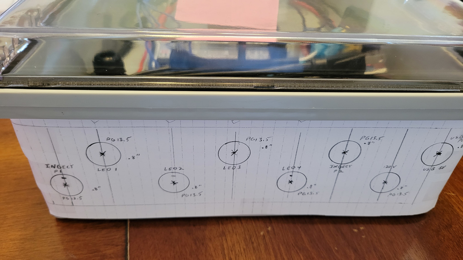
Once I was satisfied with the layout, I began to mark on the sides where the fans would fit, the power switch, antenna, power in, and power and data out cables would be. Everything on the outside was weather resistant using gaskets, and I used cable glands to secure and watertight the connector cables coming out of the bottom.
With everything in place, I created paper templates, taped them to the side, and drilled and cut holes. Unlike my typical projects, everything fit on the first try! The only issue was that the left fan was mounted a little high and came in contact with the hinge when the cover was opened. Rats! A millimeter or two lower wouldn’t impede the cover, but it still worked, and I adjusted the template for future use.
I did have to get an extension for the WiFi antenna connector to connect it to the controller board and outside.

Wiring
With wiring, the key is not to do everything at once. Take small steps and test each connection.
First was the 120-volt power cord. I added connectors to the pigtail and connected them to the toggle switch. I then wired the switch to the power supply and relay. Then I wired the 5v power to the relay and Dig Quad.
I powered it up, opened WLED on my phone, heard the click of the relay switch, and watched the indicator light turn on and off as I tested.
Perfect!
Next, I hooked up the power supply DC to the Dig Quad power input terminals using 10 AWG wires. Maybe a bit overkill but each should be able to handle 30 amperes (60 / 2 wires).
One by one I then began to hook up and test each power and data connection coming from the board to each of the data boosters and injector wires.
Once complete it looked much like a scary device (my son said a bomb), but it was beautiful!


Next Step: LEDs
I had fun hooking up some LEDs and playing with the settings. Soon I had three strips strung around my dining room.
I showed them to Snoopy, and he did a happy dance before giving me a big, wet dog kiss. Yuck!
He then pointed to the calendar, 15 days until Halloween. I still needed to install the LED strips!
Next up, Part 3: LED Lights Install
Resources
Parts List
Main
- QuinLED-Dig-Quad (I also purchased the acrylic covers)
- QuinLED-Data-Booster (I bought 4, one for each LED output)
- Mean Well RSP-320-5 300W 5 Volt Power Supply
- Mean Well MHS012 Bracket Mounting
- Mean Well TBC-09 Connection Terminal Block Cover Transparent on Digi-Key (If needed)
- uxcell M4x6mm Flat Knurled Head Fully Threaded Thumb Screws
- uxcel M4x10mm Flat Knurled Head Fully Threaded Thumb Screws
- Bergen Industries Inc PS613163 3-Wire Appliance and Power Tool Cord, 6 ft, 16AWG, 13A/125V AC, 1625w, Black
Box
- Zulkit Junction Box, IP67 Waterproof Electrical Box Hinged Clear Cover Stainless Steel Buckle Plastic Enclosure 15”x11”x5.1”/380x280x130mm
- AMPELE Cable Gland 20 Pack PG13.5 Waterproof Adjustable 6-12mm Nylon Cable Glands Joints With Gaskets, Black
- 60mm Large Air Vent, Controller Box 2.5” Vent/Fan by ChromaPixels on Etsy
- QuinLED Dig Quad Controller Meanwell/PSU Mounting Bracket by ChromaPixels on Etsy
- Prime-Line 9120780 Machine Screws, Metric, Flat Head, Phillips Drive, M2.5-0.45 x 6MM
- Hao Pro 20mm Length PCB Mounting L Feet Screws
- Alinan 4pcs 6010 60mm x 10mm 5V Dual Ball Bearings Brushless Fan 2Pin DC Cooling Exhaust Fan (I only use 2 fans, I just keep the extra for the next build. You will also need 8 screws)
- JST-XH 2.54mm 1S 2Pin Balance Plug Lead Socket Male and Female Connector with Silicone Wire Cables
- Bingfu WiFi Antenna Extension Cable RP-SMA Male to RP-SMA Female Bulkhead Mount RG316 6 inch
- YETOR Waterproof Connectors 4 Wire 16AWG Male Female Plug
- YETOR Waterproof Connectors 3 Wire 16AWG Male Female Plug
I also purchased 18AWG 2 and 3 pin waterproof nut connectors for additional connections down the line but will address those later. If you want a complete wiring product list be sure to check out the product list in the next post.
Tools for Cutting into Box
- Drill
- ¼” drill bit for antenna hole and rocker switch corners
- 2 ½” hole saw (For fans)
- 7/8” hole saw (For cable glands)
- Coping saw
Wires and Connectors
- Heat Gun for Crafts, Mini Dual Temp Hot Air Gun Tool for Epoxy Resin, Shrink Wrapping, Vinyl Wrap, Embossing, Electronics, Candle Making, Sublimation, Phone Repair & DIY While this is the one I share with my wife for arts and crafts and it works great for heat shrinks, there are more powerful, adjustable temperature guns such as this one by Porter-Cable.
- Ferrule Crimping Tool Kit Wire Crimping Tools Crimper Plier Set With Oxford Bag and 1200PCS Copper Terminal Wire Terminals
- BNTECHGO 10 Gauge Silicone Wire 5 ft red and 5 ft black Flexible Stranded Copper Wire
- BNTECHGO 14 Gauge Silicone Wire Kit 6 Color Each 3ft Flexible Stranded Tinned Copper Wire
- BNTECHGO 16 Gauge Silicone Wire Spool red 25ft and Black 25ft Flexible Stranded Copper Wire
- BNTECHGO 18 Gauge Silicone Wire Kit Red Black White Blue and Green 25ft Stranded Wire
- BNTECHGO 20 Gauge Silicone Wire Kit Red Black White Blue and Green 30ft Stranded Wire
- 16 Gauge 3 Conductor Electrical Wire 32.8ft Black PVC Case Stranded Low Voltage, 16/3 Tinned Copper Hookup Wire
- 16 Gauge 2 Conductor Electrical Wire, Red and Black Tinned Copper Hookup Wire, 50ft
- Wirefy Heat Shrink Tubing Kit – 3:1 Ratio Adhesive Lined, Marine Grade Shrink Wrap
- Wirefy Heat Shrink Wire Connectors Kit – Marine Grade Electrical Connectors
- Wirefy 110 PCS Solder Seal Wire Connectors Kit - Heat Shrink Solder Butt Connectors - Waterproof Solder Sleeves - Self Soldering Wire Connectors - Set 26-10 AWG
Ferrules are great for screw terminals as just connecting bare stranded wire to a screw terminal will quickly break the wire strands and are a no, no. I do wish there was a heat shrink version for the sleave that would provide some strain relief on the ends. However, they make solid connections.
I absolutely LOVE silicone wire. The sleeve doesn’t melt when soldering or heat shrinking and it will last in harsh weather conditions. Pre-tinned all the way through (not just the ends) is great for preventing corrosion. I still tinned the ends before soldering.
I had never used the Wirefy brand prior to this project but am quite impressed by their connectors and heat shrink offerings. The heat shrink works nicely, the connectors fit, and I always get a reliable connection. When Wirefy wasn’t available in component I needed, I wished it had been.
I had a little difficulty with the Solder Seal Wire Connectors at first, but once I got the hang of it I ended up loving them. I recommend practicing with small gauge scrap wire first, then moving up to higher gauges once you figure out the melting point. I hooked and twisted the wires together and then applied heat from a heat gun making sure not to melt the coating.
Switch and Relay
- HiLetgo 2pcs 5V One Channel Relay Module
- FILN 3Pcs Rocker Switch ON-OFF Waterproof KCD4 12V 24V 110V 220V Blue
- 1M/3.3Ft 20AWG USB 2.0 Male Plug 2pin Wire DIY Pigtail Cable 5V 5A Black USB Power Cable
- Watertight USB Connector, Copper Contact PA66 Insulator Double Female
You will also need a 5V USB to wall adapter (like for a phone charger) and a USB cable with a male end that will plug into the waterproof female connector.
Crimper and Wire Cutters
I can’t stress enough about having the proper tools for stripping and crimping. I’ve tried getting by with inexpensive (cheap) wire strippers and crimpers in the past and was never quite successful.
Unfortunately, I haven’t found a single wire cutter to rule them all. There are different types of wire jackets and while my preferred tool is the IRWIN VISE-GRIP, if for some reason it doesn’t work on a particular type of wire, I move on to the next wire cutter.
- IRWIN VISE-GRIP Wire Stripper, Self-Adjusting, 8-Inch Great for silicone and cutting the outer sheath of multi core wire. There is also a version sold by Klein.
- Klein Tools 11063W Wire Cutter / Wire Stripper, Heavy Duty Automatic Wire Stripper Tool for 8-20 AWG Solid and 10-22 AWG Stranded Electrical Wire These are my second go-to if the above wire stripper can’t get a grip.
- Klein Tools 11055 Wire Cutter and Wire Stripper, Stranded Wire Cutter, Solid Wire Cutter, Cuts Copper Wire I use this style as the last resort if the previous two can’t seem to get a grip on the wire.
Additional Tools
- Small and medium screwdrivers, flat and phillips head
- Fluke 1AC-A1-II VoltAlert Non-Contact Voltage Tester, Pocket-Sized, Voltage Detection Range 90 V to 1000 V AC, Audible Beeper, Silent Mode, Includes Batteries And 2 Year Warranty, CAT IV 1000 V Rating Indispensable for making sure you have the power switched off or troubleshooting, especially when switch wiring directions or markings are unclear.