LED Lights Installation - Holiday Doghouse Part 3
In my previous posts, I walked through remodeling an infamous red doghouse for my Christmas display—I mean Snoopy’s Christmas display. Once the sides and roof were complete and painted, I built a programmable LED controller and was ready to finish the project with addressable LED lights!
I started planning the project in spring, tore the doghouse to its frame in June, and was ready to install the lights by October. Planning early was essential because my good ol’ pal had given me a deadline of October 31, the night of the Great Pumpkin, to debut his display.
I just realized; I’m not getting paid for this! Rats!
After a few design ideas, I settled on lining the edges of the house and under the eaves with LED strip lights. The eaves, though hidden, would illuminate the doghouse, and the edges would help define it in the dark. As I built, sided, and roofed, I made sure to plan for wiring and leaving groves for LED installation. To ensure my measurements took the lights into account, I ordered the two types of LED channels before I even started work in June.
LED Channels and Diffusers
Channels and diffusers are essential for any LED project. They protect your lights from the elements, the aluminum helps dissipate heat for longer-lasting LEDs, they provide secure mounting, and, depending on the type of cover, can give your lights more of a neon look by blending the individual pixels.
I went through the Muzata store on Amazon due to the variety of options they have available. I ended up using black aluminum channels with smoky clear covers.
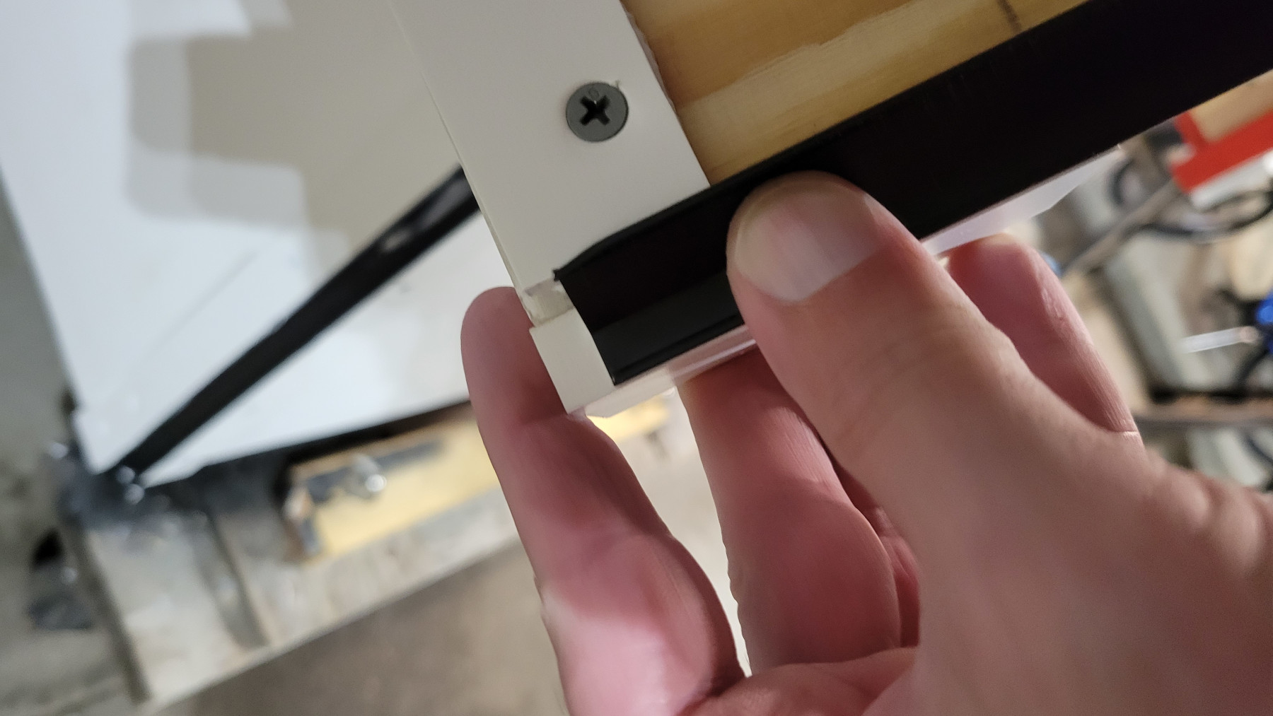
U channels were used for the eaves, the roof’s bottom edge, and along the sides of the topper. In addition, 45-degree angle V channels were used in each corner, along the roof's front and back edges, and under the eaves. For the arch, I used a flexible channel.
Incorporating black channels in the edges of the house would give it an outlined, cartoonish style. To maintain the black look, I used black-backed LED strips under the smoky clear covers, which would still reveal each LED pixel at night but blend the black edges during the day.
Smoky clear covers seemed necessary for this project as it is a holiday decoration, and traditionally, you see each point of light.
If I were lighting under shelves or other interior designs, I would use a milky white diffuser for a neon glow effect because seeing each LED would be distracting (unless you were going for a theatre marquee effect). Diffusers also help illuminate back walls without creating dark spots by spreading the light.
Addressable LED Strips
I went with BTF SK6812 RGBW (Cool White) 60 pixel per meter IP65 black strips. More about that can be found in the previous post, including information on the DigQuad light controller I used. I went with cool white to get the whitest white for Christmas and Patriotic Red, White, and Blue.
Wiring


Wiring was quite complex because I had about a dozen short runs and needed to ensure I sectioned each area off logically while maintaining a balanced load. In the end, I went with two segments: LED1 and LED2.
For power, the LED strips do not care which end you feed it. So you can connect wires to the start, middle, and end as long as you keep the positive and negative wires on their proper connections.
Power is great that way; it flows in any direction, and the more wires you have, the more amps you can safely distribute. So, for example, if you need to distribute nine amps, you could run three pairs of wires from the same source to the beginning, middle, and end of a strip, and each pair will carry three amps.
It is recommended that you inject power every 300 LEDs. If you don’t provide proper power, you could experience flickering and dimming of lights, so ensuring you have enough connections to the ends and middle with adequate gauge wire is essential.
For example, my longest continuous run was 163 LEDs along the edges of each side of the roof, so I connected power to both ends.
As some wire runs were about nine to ten feet, I used 16 AWG wire to carry power to the beginning and end of the strips to prevent voltage drop. For short connections between strips, I used 18 gauge. (AWG stands for American wire gauge.)
After some heavy calculations of length, pixels, amps, power consumption, and safe distribution over 16 gauge wires, I developed a design that would give it a glow under the eaves and outline the house’s corners, door, and roof.
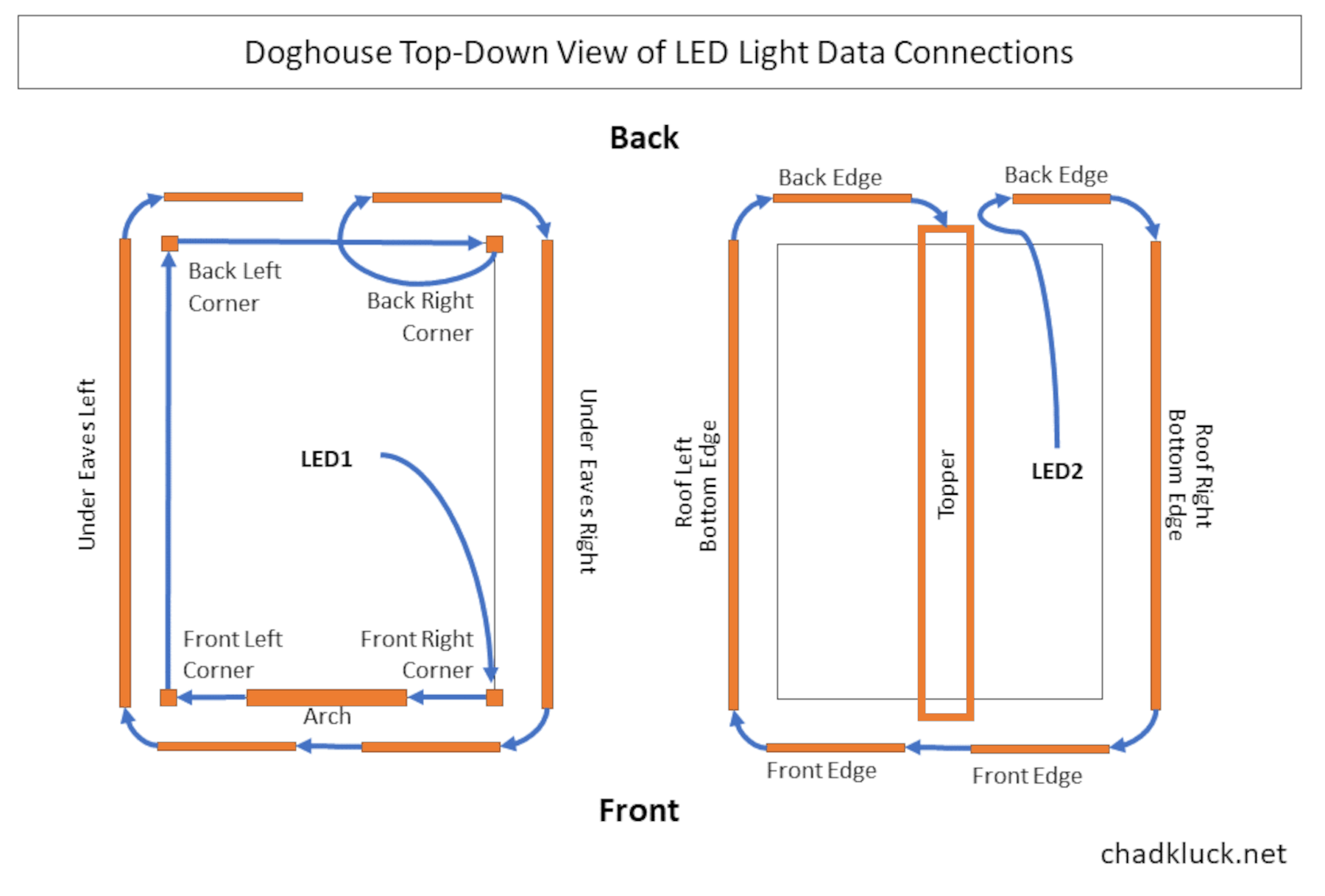
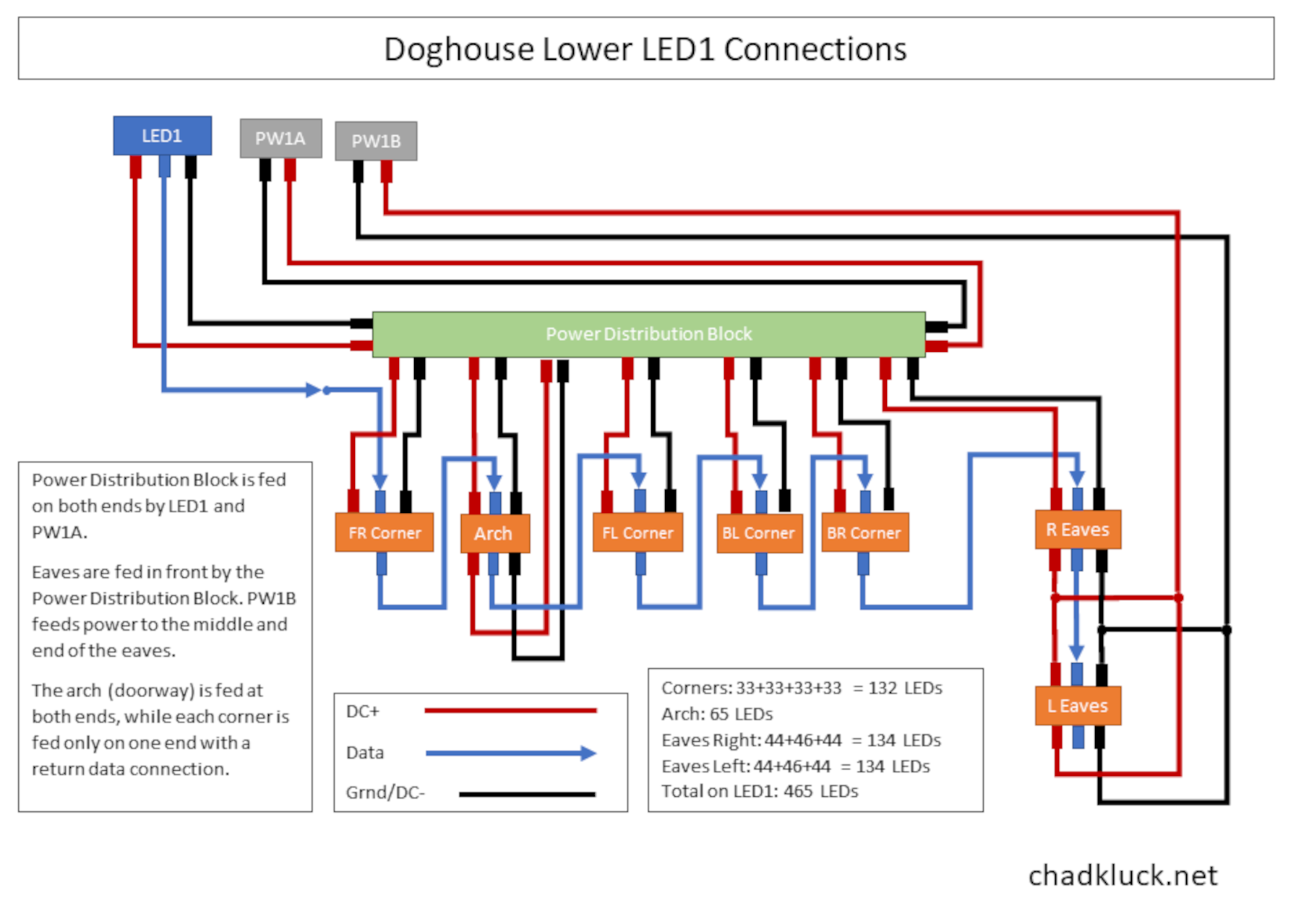
The four corners, door arch, and eaves were all on one segment labeled LED1. I used a power distribution block with two power inputs and seven outputs. Power was supplied to the bottom of each corner using a pair of 16-gauge wires. The arch was fed from both ends, and the eaves were divided into left and right sections. I ran power to the start and end of each side of the eaves.
Also, with each of the four corners, since power was fed from the bottom, I needed to run an exit data wire from the top, back down along the strip in the channel, and run it to the next strip.

On the LED2 segment, I wired together the roof and topper. Like with the eaves, the roof was comprised of two sections, left and right, each receiving power at the start and end of the strips.

Data and Addressing
Though power can be fed anywhere along the strips, data must always flow in one direction, and a data wire must always run from the end of one strip to the beginning of the next in the sequence.
The way addressable LEDs work is quite simple. First, a data message with instructions for each LED is sent down the line.
For example:
- LED 1: Red at 90% brightness
- LED 2: Blue at 90% brightness
- LED 3: OFF
- LED 4: Red at 90% brightness
- And so on.
- LED 901: Red at 90% brightness
- LED 902: Blue at 90% brightness
- LED 903: OFF
- LED 904: Red at 90% brightness
- And so on.
Okay, so the controller spits out all these instructions, but how does each LED know which instruction to listen for? It’s pretty simple: They count off as if they were lined up in gym class.
As the instructions go down the data wire, each LED receives the instructions with the number of the previous LED. So, for example, if the previous LED was number 389, the LED receiving the instruction knows it is LED number 390, takes its corresponding instruction from the list, and passes its identification number to the next LED, which would know it is LED number 391.
Because of this count-off, it is essential to always run the data line between strips.
Soldering and Connections

In the past, I’ve never been entirely successful when soldering, so I used good, weatherproof crimps and solder butt connectors where I could.
However, for connecting wires to the strips, you will need to solder good connections, and I wasted an entire weekend with a bunch of bad connections I had created. I had the arch, and each corner installed and was halfway through the eaves when the lights began to flicker before going to a steady, full-on white. They’d work for a while before going erratic. Luckily, I was able to salvage the LEDs, but it set me back an entire week. Rats!
I overcame my lousy solder jobs by doing two things: ditching soldering flux and purchasing a temperature-adjustable soldering iron.
I had not been using a cheap soldering iron, it was a Weller, but I couldn’t determine its temperature or adjust it. Sometimes I’d be soldering just fine, and the next moment, I couldn’t get the solder to flow. I also learned that flux is nasty to PCB and the strips.
While I like getting new toys, especially at the onset of projects, there comes a tipping point where the new tool purchases begin to stress the budget.
However, boy, was it worth it! With a new temperature-adjustable soldering station, 650-680 degrees Fahrenheit gave me a consistent working temperature, and I could quickly compensate for lost time. Also, no bad connections!
To protect the LEDs and chips as I soldered wires to the strips, I used heat clamps, and I can’t recommend them enough! I placed them right between the chip and the strip’s soldering pads, and even though the wire in my hand heated up, everything beyond the clamp was as cool as a cucumber!
I used the technique for soldering IP65 strips described in a Smart Home Hookup video by cutting away a portion of the silicone cover, soldering, and using hot glue and a transparent heat shrink tube to fill the gap. I also used Liquid Tape on the ends before applying hot glue and heat shrink tubing there as well.
As I moved connections around, I connected leads to feeders using lever wire nut connectors (link in the parts section). They are still in use even after I cleaned up many of the connections with waterproof connectors. I’ll most likely replace them before next season. The lever connectors are great because it allows you to move things around, experiment, and test before creating more permanent connections with solder connectors or plugs.

Installation
Weather and water resistance were crucial in how I installed the wiring and lights on the exterior of the doghouse. The LED strips were water-resistant, and I ensured my connections were waterproof. The channels were sealed at the top, and I left holes for the wires in the bottom endcaps unsealed as they were too small for bugs and would allow any moisture that accumulated inside the channel to escape. (I also ended up drilling small egress or weep holes in the horizontal channels to let any water out—more on that later.)
As mentioned earlier, I fed the corners from the bottom so that the tops would remain sealed and moisture could exit through the bottom end cap. IP65 LEDs are water resistant, water can flow over them, but they cannot be submerged.
With a clear idea of how I would feed the wires into the channels, I could begin drilling holes to feed the wire from the outside to the inside, crossing my fingers that I didn’t hit anything that would obstruct a wire feed and force me to drill another hole! The good news is that I didn’t hit any obstructions, and the doghouse didn’t look like Charlie Brown’s ghost costume with a bunch of extra holes!
I covered the external wires with lengths of heat shrink tubing from a roll, careful not to melt the channels’ plastic end caps or harm the doghouse's exterior paint. I used a piece of aluminum foil between the wire and the house to help deflect some of the heat.

I used a Dremel to cut the aluminum channels. I would wrap painter’s tape around the channel and mark the cut with a fine point marker. I’d then cut and use a file to eliminate any burs.
Installing the channel diffusers was done last. I wanted to make sure everything fit and worked. I used the same painter’s tape and marker technique to cut the diffusers and made the cut with a hobby saw and miter.

Topper
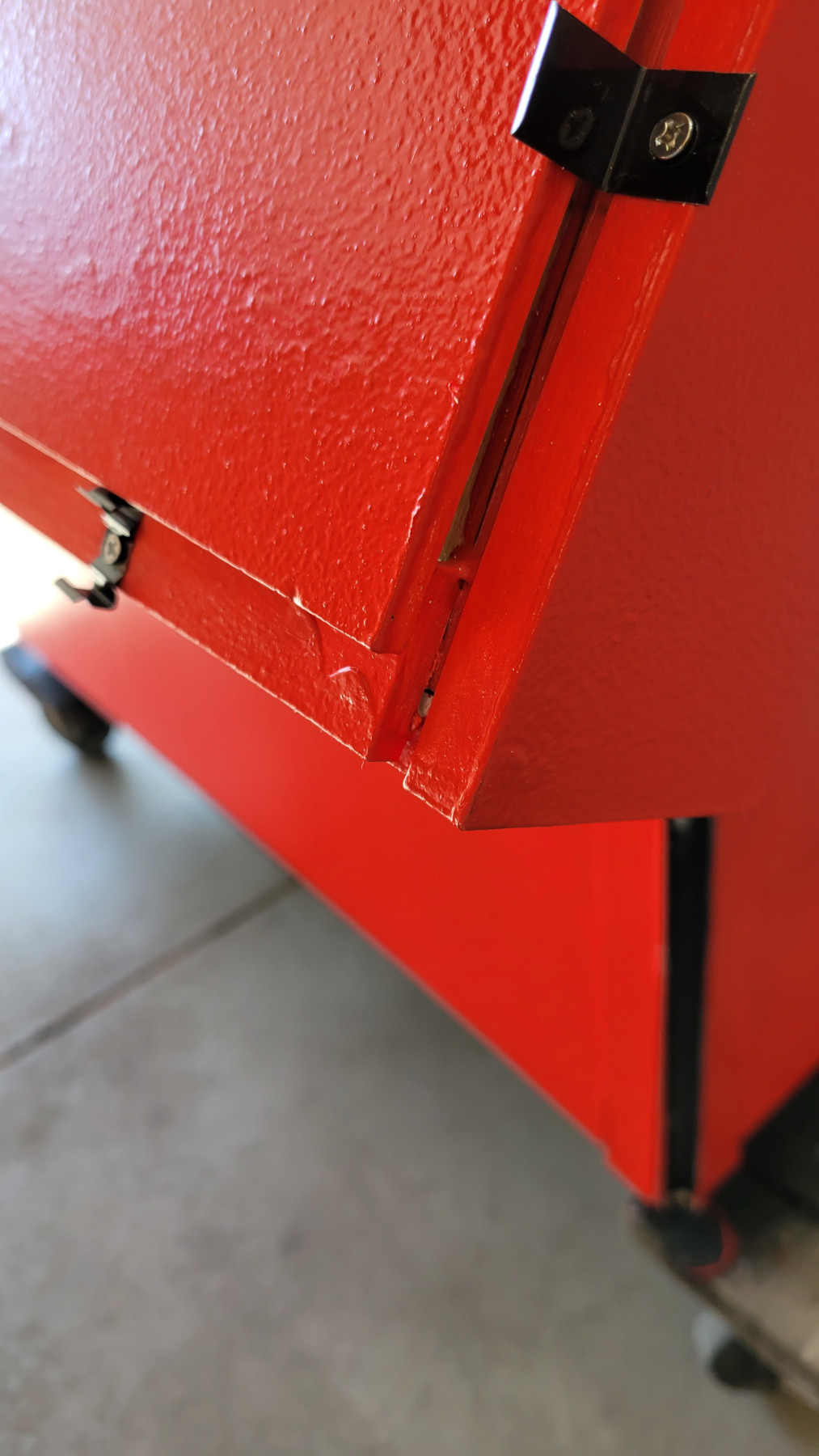
I left the topper for last and didn’t complete it until after Halloween. The roof ridge of Snoopy’s doghouse never really comes to a point and is flat, allowing for a spot to grab a good night’s sleep.
A flat piece is also perfect for this project as it provides room for the roof sides to swing up and acts as a nice weather cap to prevent rain and melting snow from coming into the doghouse.
I tried a few ideas where the cap attaches to the roof with hinges but could never get it to work on top of the roof sides, which were also hinged. So, I finally settled on building a completely removable topper, which would be a pain to remember before lifting the roof, but doable.
The topper also needed to house lights along its sides and therefore have a way to wire it. It also required a somewhat low profile, not too bulky or sticking up too high, providing a function as a roof cap in harsh weather.
To create it, I used PVC panels, providing room for a channel of lights, a pigtail connector to come out underneath for an easy connection to power and data, and lined the bottom with weather stripping.

Sealing
I wanted to make sure no water could make its way into cracks, form into ice, create mold, or short out any electrical, so I sealed any gaps between the channels and dog house with clear silicone. I also smeared some silicone over areas where water might run over the edges of the channels.
I chose clear silicone because the doghouse was painted, and the transparency wouldn’t affect the lights. However, despite the promise of working in cold weather, I wasn’t too satisfied with how the silicone seemed to set in the 40-degree garage, and I encourage you to get all your sealing done before the weather drops below fifty.
I waited until after Halloween to seal it up since it wouldn’t be out overnight or in the elements until Thanksgiving.
Finished!
Though the topper wasn’t complete by the deadline, the lights were fully functional and programmed various green, orange, and purple light sequences for its debut on Halloween!
Satisfied, Snoopy donned his World War I Flying Ace costume and went off to fight the Red Baron.
What? It wasn’t a costume? Snoopy is a World War I Flying Ace? Good grief.


Well, Halloween was a success, and I received many compliments. The doghouse was again set out in my yard the day after Thanksgiving, just in time for Charles Schultz’s 100th birthday and the start of the Christmas and winter season display.
I programmed several light patterns for Christmas, and since the doghouse stays out until mid-March (or April if the snow doesn’t go away), I marked other holidays as well, such as New Year’s, Valentine’s, St. Patrick’s, Easter, and local hockey team colors. It was nice being able to tweak each program from the comfort of my house, looking out the front window and connecting to the controller via Wi-Fi from my phone.


In the several months it has been outside, there was only one issue: water collected in the horizontal strip at the bottom of the roof. Luckily, I immediately noticed it, disconnected the power to the roof, and rerouted the data line to the roof topper. I drilled three holes along the bottom edge of the channel to let the water out and will need to wait until spring to see how I can recover as the strip seems dead. I can’t stress the importance of placing water egress/weep holes at the gravitational bottom of each channel and sealing up anywhere water may be running over the cover.
Ultimately, I’m thrilled with how it turned out and the overall appearance when lit. While it has the same frame, it does not look like the doghouse I built 13 years ago with limited tools, supplies, and knowledge.
Lastly, I must say, “Merry Christmas, Charlie Brown!” and “Happy 100th Birthday, Charles Schulz!”
Photos


Resources
Parts List
LEDs
- Muzata 6Pack 3.3FT/1M V-Shape LED Channel System with Crystal Smoky Clear Lens, Black Aluminum Extrusion Profile Housing Track for Strip Tape Lights
- Muzata 10 pack 6.6FT/2M Black LED Channel System with Crystal Smoke Transparent Clear Cover Lens, Aluminum Track
- Muzata 6PACK 3.3FT/1M Flexible LED Channel with Crystal Smoke Black Cover Lens, Black Bendable Aluminum Profile Housing for Strip Tape Light, Anodized
- Muzata 12 Pack Caps and Mounting Clips for V Shape V1SW LED Aluminum Channel System (Extra channel brackets which I spray painted black because, unlike the extra U clips, V clips didn’t come in black.)
- Muzata 12Pack Black LED Channel Mounting Clips and End Caps for Muzata Black U1SW U-Shape Aluminum Channel (Extra channel brackets)
- BTF-Lighting SK6812 RGBW (cool white) Addressable LED Strip Waterproof IP65 60 pixels per meter (black backing) on AliExpress
Wires and Connectors
Most of the wires and connectors in this list are repeated from the previous post.
- Heat Gun for Crafts, Mini Dual Temp Hot Air Gun Tool for Epoxy Resin, Shrink Wrapping, Vinyl Wrap, Embossing, Electronics, Candle Making, Sublimation, Phone Repair & DIY While this is the one I share with my wife for arts and crafts and it works great for heat shrinks, there are more powerful, adjustable temperature guns such as this one by Porter-Cable.
- Ferrule Crimping Tool Kit Wire Crimping Tools Crimper Plier Set With Oxford Bag and 1200PCS Copper Terminal Wire Terminals
- BNTECHGO 18 Gauge Silicone Wire Kit Red Black White Blue and Green 25ft Stranded Wire
- BNTECHGO 20 Gauge Silicone Wire Kit Red Black White Blue and Green 30ft Stranded Wire
- 16 Gauge 3 Conductor Electrical Wire 32.8ft Black PVC Case Stranded Low Voltage, 16/3 Tinned Copper Hookup Wire
- 16 Gauge 2 Conductor Electrical Wire, Red, and Black Tinned Copper Hookup Wire, 50ft
- Wirefy Heat Shrink Tubing Kit – 3:1 Ratio Adhesive Lined, Marine Grade Shrink Wrap
- Wirefy Heat Shrink Wire Connectors Kit – Marine Grade Electrical Connectors
- Wirefy 110 PCS Solder Seal Wire Connectors Kit - Heat Shrink Solder Butt Connectors - Waterproof Solder Sleeves - Self Soldering Wire Connectors - Set 26-10 AWG
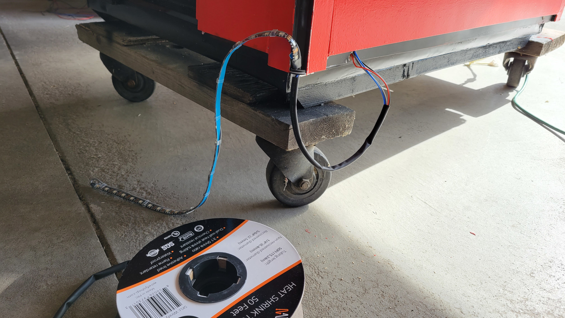
- Wirefy 1/4" Heat Shrink Tubing - 3:1 Ratio - Adhesive Lined - Industrial Marine Heat Shrink Tubing Roll - Black - 50 Feet Roll
- Wirefy 3/8" Heat Shrink Tubing - 3:1 Ratio - Adhesive Lined - Industrial Marine Heat Shrink Tubing Roll - Black - 50 Feet Roll
- 1/2" Wire Heat Shrink Tube Polyolefin Marine Heat Shrink Tubing 3:1 Dual Wall Adhesive-Lined Electric Tubes for Cable Wires Black Red White Clear, 5 F
- smseace 30 Pcs 3 Port Two-Way Lever Wire Nut Conductor Compact Connectors Quick Terminal Block 28-12 AWG
- smseace 50 Pcs Lever Wire Nut Conductor Compact Connectors Quick Terminal Block for 2 Circuit Inline Splices 28-12 AWG
- smseace 50 Pcs Lever Wire Nut Connector Assortment Connectors
Waterproof Nut Connectors
I used a 3-pin if I ran power and data, a 2-pin for power only, and a 4-pin if I ran two pairs of power wires out. If I were running a long wire, I would use 16 AWG, and if I were connecting to a strip or in between strips (less than 12” of lead), I’d use 18 AWG. These all use the same connector, so you can connect a 16 AWG to an 18 AWG if they have the same pin count. I also created a Y connection to split a 4-pin into two 2-pins.
- BTF-LIGHTING 2 Pin Electrical Connector 18 AWG IP65 Male Female Connector 7.87in/20cm Extension Cable for Car, Truck, Boat, Indoor/Outdoor LED Strip Light
- BTF-LIGHTING 3 Pin Electrical Connector 18 AWG IP65 Male Female Connector 7.87in/20cm Extension Cable for Car, Truck, Boat, Indoor/Outdoor LED Strip Light
- YETOR Waterproof Connectors 2 Wire, 16 AWG Male Female Plug LED Connector with 2Pin Waterproof Connectors, IP68 20CM Extension Cable for Car, Truck, Boat, Indoor/Outdoor LED Strip Lights,(5Pairs)
- YETOR Waterproof Connectors 3 Wire 16 AWG Male Female Plug
- YETOR Waterproof Connectors 4 Wire 16 AWG Male Female Plug
Crimper and Wire Cutters
I can’t stress enough about having the proper tools for stripping and crimping. I’ve tried getting by with inexpensive (cheap) wire strippers and crimpers but was never entirely successful.
Unfortunately, I haven’t found a single wire cutter to rule them all, as some deal with different types of wire jackets better than others. While my preferred tool is the IRWIN VISE-GRIP, if it doesn’t work on a particular kind of wire, I move on to another style of wire cutter.
- IRWIN VISE-GRIP Wire Stripper, Self-Adjusting, 8-Inch Great for silicone and cutting the outer sheath of the multi-core wire. There is also a version sold by Klein and Gardner Bender GS-394.
- Klein Tools 11063W Wire Cutter / Wire Stripper, Heavy Duty Automatic Wire Stripper Tool for 8-20 AWG Solid and 10-22 AWG Stranded Electrical Wire These are my second go-to if the above wire stripper can’t get a grip. Also, a version by Gardner Bender SE-92 but it doesn’t have a wire length stopper
- Klein Tools 11055 Wire Cutter and Wire Stripper, Stranded Wire Cutter, Solid Wire Cutter, Cuts Copper Wire I use this style as the last resort if the previous two can’t seem to get a grip on the wire. Usually, I use it to slice through the jacket and then use one of the other strippers to finish the job. Gardner Bender GS-370
I don’t use the crimping notches found on the wire cutters. Instead, I prefer a ratcheting-style crimper as I am guaranteed a secure connection.
Tools
- Goot Heat clip H-2SL
- Weller WE1010NA Digital Soldering Station
- AUSTOR 0.6mm Lead-Free Solder Wire with Rosin Core
- NEIKO 01902 Adjustable Helping Hand with Magnifying Glass, Third Hand Solder Aid
- Hack saw or Dremel
- Hobby saw
- Drill
- Pliers, screwdrivers, nippers, etc. A lot of basic tools.